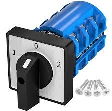
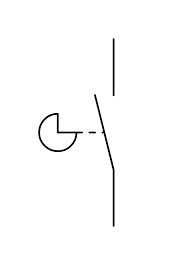
What is Electrical Symbol for Cam Switch


In Single line Diagram?
In a Single Line Diagram (SLD), a cam switch is typically represented by a simplified symbol that indicates its function and operation. It may look like one of the following:
-
Rotary Switch Symbol:
- A circle or rectangle with a diagonal line or lever to indicate it is a manually operated switch.
- Labels such as CS (Cam Switch) or specific position numbers (e.g.,
1-2,1-3) might be included to denote its operation.
-
Switch Symbol with Positions:
- A single contact symbol showing the possible positions (e.g.,
Ofor open,Ifor closed, or numbers representing multi-position switching). - Additional text or annotations might describe the function, like Selector Switch.
- A single contact symbol showing the possible positions (e.g.,
-
Functional Label:
- Often, the cam switch is annotated with its purpose, such as Isolator, Control Switch, or a specific load/breaker it controls.
Example:
In an SLD for a motor control center, a cam switch might be shown like this:
- A simple manual switch icon with annotations like “CS-Motor1” (for controlling Motor 1).
- It may also be combined with auxiliary components like indicators or breakers in the same schematic.
Is there something to watch when drawing cam switch in single line diagram
Yes, when drawing a cam switch in a Single Line Diagram (SLD), there are a few considerations to ensure clarity and correctness:
Key Considerations:
-
Symbol Standardization:
- Use a recognized symbol, such as the rotary switch symbol (circle with a diagonal line) or any symbol specified by IEC, ANSI, or other applicable standards.
- Annotate it properly (e.g., label as
CSfor “Cam Switch”) to make its purpose clear.
-
Function Representation:
- Indicate the function of the cam switch (e.g., “ON/OFF,” “Selector Switch,” or specific connection points like
1-2,1-3). - Include position states if applicable (e.g.,
0,I,IIfor different positions).
- Indicate the function of the cam switch (e.g., “ON/OFF,” “Selector Switch,” or specific connection points like
-
Connection Points:
- Ensure that the connections to the cam switch are accurately drawn.
- Clearly show the input and output connections to avoid ambiguity.
-
Annotation:
- Include a descriptive label or name to indicate the cam switch’s role in the circuit, such as:
- Control switch for a motor
- Changeover switch for a transformer
- Add additional details if needed, like current rating or application context.
- Include a descriptive label or name to indicate the cam switch’s role in the circuit, such as:
-
Placement:
- Place the cam switch symbol logically within the SLD to reflect its actual position in the circuit.
- Avoid crossing lines unnecessarily to maintain clarity.
-
Multi-Position Switches:
- If the cam switch has multiple positions, label each position to match its configuration in the real circuit.
- Use a clear legend or table if the diagram becomes complex.
-
Associated Components:
- If the cam switch operates other components (e.g., motors, transformers, or breakers), draw clear connecting lines to these elements.
- Indicate auxiliary contacts if applicable.
Do I need to watch the voltage I am connecting to
What if I have 1000V DC
If your system involves 1000V DC, special considerations are necessary for the selection, installation, and use of a cam switch due to the unique characteristics of DC. Here’s what you need to account for:
Key Considerations for 1000V DC
-
Switch Voltage Rating:
- The cam switch must be explicitly rated for at least 1000V DC. Many switches rated for AC may not be suitable for high-voltage DC applications.
- Look for switches certified for DC use and verify the voltage and current ratings for DC operation (often lower than for AC).
-
Arcing in DC Systems:
- Unlike AC, DC does not have natural zero-crossing points, making arc extinguishing more challenging.
- Ensure the switch has features to suppress or extinguish arcs, such as magnetic blowouts or arc chambers.
-
Current Rating:
- Confirm the switch can handle the current in your circuit at 1000V DC without overheating or causing excessive wear on the contacts.
-
Contact Spacing:
- DC switches require wider contact spacing to prevent arcing during switching. Ensure the switch design meets this requirement.
-
Polarity:
- Verify whether the cam switch is polarity-sensitive. Some switches designed for DC systems have directional markings for correct wiring.
-
Safety Standards:
- Ensure the cam switch complies with standards like IEC 60947-3 (for switches and disconnectors) or equivalent, which address high-voltage DC.
-
Overvoltage Protection:
- Incorporate surge protective devices (SPDs) or similar measures to handle transient overvoltages.
Practical Steps for SLD
-
Symbol Annotation:
- Clearly label the cam switch in the diagram, including:
- Its voltage rating (e.g., 1000V DC).
- Its current rating.
- The function (e.g., disconnect, selector).
- Example:
CS (1000V DC, 50A)
- Clearly label the cam switch in the diagram, including:
-
Location in the Circuit:
- Place the cam switch in a location where it will not experience excessive transient voltages or currents beyond its rating.
-
Associated Protection Devices:
- Add fuses, circuit breakers, or SPDs nearby in the SLD to enhance protection and compliance.
-
Manufacturer Data:
- Include part numbers or manufacturer specifications in the SLD documentation to ensure the correct switch is used.
Example Cam Switch Models
Look for cam switches specifically rated for high-voltage DC applications from reputable manufacturers like:
- ABB
- Schneider Electric
- Siemens
- Eaton

0 Comments