What is Main Earthing Terminal (MET)

by Blog

The Main Earthing Terminal (MET) is a crucial component in an electrical installation that serves as a central connection point for all earthing conductors within a system. It ensures that all parts of the installation have a common ground reference, which is essential for safety, equipment protection, and compliance with electrical standards.

Functions of the MET:

  1. Electrical Safety:

    • It provides a pathway for fault currents to flow safely to the ground, reducing the risk of electric shocks or fire.
  2. Common Connection:

    • It interconnects all earthing systems, such as the protective earthing (PE), equipotential bonding, and functional earthing, into one unified system.
  3. Fault Management:

    • It facilitates the safe disconnection of protective devices (like circuit breakers or fuses) by providing a low-impedance path to the ground during faults.
  4. Compliance:

    • It ensures the electrical installation complies with relevant safety standards, such as IEC, NEC, or BS standards.

Components Typically Connected to the MET:

  • Protective Earthing (PE) Conductors: Connects metal parts of equipment to the MET.
  • Equipotential Bonding Conductors: Links different metallic systems (e.g., water pipes, gas pipes) to prevent potential differences.
  • Main Earth Electrode Conductor: Connects the MET to the physical earth (via earth rods, plates, or other electrodes).
  • Lightning Protection System: Ensures safe dissipation of lightning strikes.
  • Functional Earthing Conductors (if required): For grounding certain electronic components or systems.

Location of the MET:

The MET is usually located near the main distribution board, where the incoming supply enters the building. In larger installations, it may be part of the Main Earthing Bar (MEB) or Earth Bar, which serves a similar function on a larger scale.

Standards and Best Practices:

  • The MET must be robust, corrosion-resistant, and capable of handling high fault currents.
  • It should be easily accessible for maintenance and testing.
  • Clear labeling and proper segregation of conductors are required to avoid confusion during inspection or troubleshooting.

The MET is a foundational element in ensuring the electrical safety and reliability of any installation.
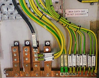
MET point

Is There Any Guidelines How to Connect to MET? Any Rules to Follow?

Yes, there are guidelines and rules for connecting to the Main Earthing Terminal (MET) to ensure safety, functionality, and compliance with electrical standards. The rules are typically defined by national and international standards like the IEC 60364, BS 7671 (IET Wiring Regulations), or NEC (National Electrical Code). Here are the key guidelines:

1. General Requirements:

  • Location: The MET should be installed in an accessible location, typically near the main distribution board or at the entry point of the electrical supply.
  • Labeling: The MET must be clearly labeled for identification, such as “Main Earth Terminal” or “MET.”
  • Connection Capacity: The terminal must be large and robust enough to accommodate all incoming earth conductors, including the main earth electrode conductor, protective earth (PE) conductors, and bonding conductors.
  • Material: The MET should be made of conductive, corrosion-resistant material (e.g., copper or brass).

2. Conductors to Connect:

  • Main Earthing Conductor:

    • Connects the MET to the earth electrode or earthing system.
    • The size of the conductor should meet the standards for fault current capacity and impedance requirements.
  • Protective Earthing (PE) Conductors:

    • Connect all exposed conductive parts of electrical equipment to the MET.
    • Ensure proper sizing based on the current rating of the circuits they protect.
  • Equipotential Bonding Conductors:

    • Link metallic parts like water and gas pipes, structural steel, and other systems to the MET.
    • Should be sized according to local regulations to equalize potential during faults.
  • Functional Earthing Conductors (if applicable):

    • For specialized systems like telecommunications or lightning protection.
    • These connections must be carefully designed to prevent interference.
  • Lightning Protection System:

    • If applicable, it should connect to the MET for safe dissipation of lightning strikes.
    • Ensure compliance with standards like IEC 62305 for lightning protection.

3. Connection Guidelines:

  • Secure Connections:

    • All connections to the MET must be mechanically secure and electrically sound to handle high fault currents.
    • Use appropriate lugs, clamps, or terminals that resist loosening over time.
  • Low Impedance:

    • Connections must provide a low-resistance path to the earth to ensure effective fault current dissipation.
    • Avoid unnecessary joints; if joints are unavoidable, they must be mechanically and electrically sound.
  • Testing Points:

    • Ensure there is a provision for testing the earth connection, such as a disconnectable link between the MET and the earthing electrode.
  • Corrosion Protection:

    • If the MET is in a corrosive environment, it must be adequately protected (e.g., through galvanization or enclosure in a weatherproof box).

4. Sizing Conductors:

Conductor sizes are based on the system’s fault current rating, earthing system type, and local regulations. Examples:

  • Main Earthing Conductor: Must handle the maximum expected fault current without overheating.
  • Protective Earthing (PE) Conductors: Sized according to the circuit protective devices (e.g., BS 7671 Table 54.7).
  • Equipotential Bonding Conductors: Typically 50% of the size of the largest conductor connected to the MET but not less than a minimum size (e.g., 6 mm² copper for TN systems).

5. Compliance and Testing:

  • Standards Compliance:
    • Follow the applicable standards for your region (e.g., IEC 60364, BS 7671, or NEC).
  • Inspection and Testing:
    • Test the continuity of the earthing system to ensure all connections are sound.
    • Measure the earth electrode resistance to confirm it meets the required specifications (e.g., ≤ 1 ohm for critical installations).
  • Record Keeping:
    • Maintain detailed records of the earthing system, including conductor sizes, connection points, and test results.

6. Earthing System Type Considerations:

  • For TN-S Systems: The MET connects the earthing conductor to the neutral of the supply transformer.
  • For TN-C-S Systems (PME): Additional care is required to ensure bonding of all metallic services.
  • For TT Systems: The MET connects to an independent earth electrode, and an RCD is essential for protection.
  • For IT Systems: Insulation monitoring devices (IMDs) must be integrated, and the MET handles fault discharges through high-impedance earthing.

Summary of Key Rules:

  • Use Proper Sizing: Conductors must meet the standard’s minimum cross-sectional area.
  • Ensure Secure Connections: Prevent loose connections that could lead to high impedance or failure.
  • Minimize Impedance: Aim for the lowest possible resistance for efficient fault current flow.
  • Provide Testing Access: Include a disconnectable link for periodic testing.
  • Follow Standards: Adhere to regional and international codes for safety and compliance.

Proper connection to the MET is vital for the safety and reliability of any electrical installation.

What Material Can be Used for MET?

The Main Earthing Terminal (MET) must be made from materials that ensure electrical conductivity, mechanical strength, and durability over time, even in challenging environments. Here are the commonly used materials for MET and their characteristics:

1. Copper

  • Why Use Copper?
    • Excellent electrical conductivity.
    • Highly resistant to corrosion.
    • Mechanically strong and durable.
    • Suitable for various environmental conditions, including outdoor or corrosive environments.
  • Common Forms:
    • Copper bars, plates, or strips.
    • Tinned copper (for enhanced corrosion resistance).

2. Brass

  • Why Use Brass?
    • Good electrical conductivity (not as high as copper but sufficient for MET applications).
    • Highly resistant to corrosion, especially in wet or damp environments.
    • Mechanically robust.
  • Common Applications:
    • Often used in MET terminals, clamps, or connectors in moderate environments.

3. Aluminum

  • Why Use Aluminum?
    • Lightweight and cost-effective compared to copper.
    • Reasonable electrical conductivity (lower than copper but suitable for many applications).
  • Challenges:
    • Prone to oxidation, which can increase resistance at the contact points.
    • Requires special anti-oxidation paste and proper maintenance.
  • Suitability:
    • Best for dry, controlled environments or when weight and cost are key considerations.

4. Galvanized Steel

  • Why Use Galvanized Steel?
    • Mechanically strong and cost-effective.
    • Corrosion-resistant due to galvanization (zinc coating).
  • Challenges:
    • Lower electrical conductivity compared to copper or aluminum.
    • Not ideal for high-fault current applications.
  • Suitability:
    • Used as MET in structural earthing systems where mechanical strength is more critical than electrical conductivity.

5. Stainless Steel

  • Why Use Stainless Steel?
    • High resistance to corrosion, especially in marine or highly corrosive environments.
    • Mechanically robust.
  • Challenges:
    • Relatively low electrical conductivity compared to copper or aluminum.
  • Suitability:
    • Used in environments where corrosion is a primary concern and current flow is secondary.

6. Tinned Materials (Copper, Brass, or Aluminum)

  • Why Use Tinned Materials?
    • Tinning provides an extra layer of protection against corrosion and oxidation.
    • Ensures reliable performance in harsh or outdoor environments.

Selection Criteria for MET Materials:

  1. Electrical Conductivity:

    • High conductivity materials like copper are preferred for efficient fault current dissipation.
  2. Corrosion Resistance:

    • Materials must resist corrosion to maintain long-term functionality, especially in damp, marine, or industrial environments.
  3. Mechanical Strength:

    • The MET must withstand physical stresses, including the connection of multiple heavy conductors.
  4. Cost and Availability:

    • Copper is ideal but may be expensive; alternatives like aluminum or galvanized steel are chosen in cost-sensitive projects.
  5. Environmental Suitability:

    • Use stainless steel or tinned materials in corrosive environments.
    • Galvanized steel or brass for moderate environments.
    • Aluminum or copper for dry, controlled environments.

Standards and Recommendations:

  • IEC 60364: Suggests using materials with adequate conductivity and corrosion resistance.
  • BS 7671: Recommends using copper or tinned copper for METs in most installations.
  • NEC (National Electrical Code): Specifies the use of listed and approved materials for grounding and bonding.

Practical Tip:

The material of the MET should match or exceed the conductivity and durability of the connected conductors. For critical applications, copper or tinned copper is often the best choice.

Hi,

I am Frank and my wish is to give you the best experience about the electrical engineering field.

The article is written by me where I share my passion for this topic and I hope I have shed some light to you on this topic.

If you would like to learn more about me check the about page here.

Electrical Enegineering

Check all Electrical Engineering Categories

Engineering

Engineering

0 Comments

Submit a Comment

Your email address will not be published. Required fields are marked *